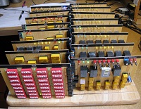
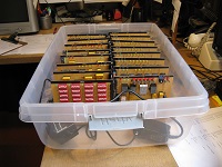
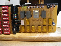
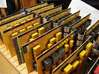
Many years ago, before affordable computers were available, I tried to build one out of relays. Unfortunately that never got much beyond the light-flasher stage. Recently, a friend gave me hundreds of reed relays, and that early goal got renewed. Here's the result.
Of course a relay computer can't begin to compete with modern machines, but it can reveal some of the mysteries of how they work. Mechanical relays are easy to understand. The RR6 sports 157 LEDs that bring to light the contents of its registers and the signals that manipulate those contents.
Video showing historic moment when the RR6 ran its first program.
.
The program memory (PROM: Programmable Read-Only Memory) consists of 32 8-bit words implemented with 32 DIP switches.
The clock speed is adjustable. The RR6 currently runs reliably up to three instructions per second (three micro MIPS). All instructions execute in two steps, and each step is four clock cycles. Clocks can also be executed one at a time using a momentary toggle switch.
User input: six front panel toggle switches (R7/IN).
User output: 7-segment display (R4 + Carry) and 157 LEDs that show the state of all registers and most of the logic.
The design is similar to a scaled down Microchip PIC16C5X. Other influences are from the 6502, x86, and John Doran's D16/M . Using a register, rather than a stack, to hold the return address for a subroutine call is from ARM processors. The RR6 has 26 instructions, described below.
About 640 diodes (1N4004 + 12 Schottky 1N5817) are used to implement OR logic circuits and to suppress kickback voltage on each relay.
Two wall-wart power adapters are used: 5 volts for relays, and 9 volts for the Clock relay flip-flops and for most of the LEDs (to reduce the load on the 5 volt 6 amp supply).
Most of the electronic components came from Jameco.com.
The computer is breadboarded on an actual breadboard that came from Target. The plastic (Hefty) case is also from Target, and it nicely fits the breadboard.
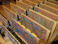
Sixteen perfboards from Radio Shack mount in slots cut in the breadboard. Radio Shack still exists on the Internet, and their perfboards at only $2 apiece were a big influence on the overall physical construction.
Labels for the boards were made using Windows WordPad (Lucinda Console with black highlighting) then glued on with rubber cement.
Bare wire is used to connect nearby components, much like a printed circuit board trace. Wire-wrap wire is used for longer connections and for the ribbon cable header connectors. The ribbon cables form a common bus that interconnects the boards.
A goal was to make a computer using pre-WWII components. Temptations to simplify things by using transistors or ICs were resisted. However, it was just too tempting to use LEDs instead of power consuming incandescent bulbs and switching power supplies instead of heavy iron transformers.
LDI = load accumulator (AC) with immediate value (0-63)
JMP = jump to address (0-31)
JSR = jump to subroutine at address (0-31) and store return address in link register (LR)

LOD = load accumulator (AC) with value in register (R0-R7)
STO = store value in accumulator (AC) into register (R0-R7)

ADD = add value in register (R0-R7) to accumulator (AC)
SUB = subtract value in register (REG: R0-R7) from accumulator (AC)
AND = bitwise AND operation: AC <- AC & REG
IOR = bitwise (inclusive) OR operation: AC <- AC | REG
XOR = bitwise exclusive OR operation: AC <- AC ^ REG

NOT = bitwise NOT operation: REG <- ~REG
INC = increment register: REG <- REG + 1
DEC = decrement register: REG <- REG - 1
DSZ = decrement register REG and skip next instruction if result is zero
CLR = clear (zero) register: REG <- 0
ROL = rotate register REG left, including Carry status bit
ROR = rotate register REG right, including Carry status bit
RET = return from subroutine

CLC = clear Carry status bit
SEC = set Carry status bit
SCC = skip next instruction if Carry bit is clear
SCS = skip next instruction if Carry bit is set
SEQ = skip next instruction if equal zero (if Zero status bit is set)
SNE = skip next instruction if not equal zero (if Zero status bit is clear)
SAC = set accumulator (AC) with Carry bit (0 or 1)
HLT = halt running by stopping the Clock (flip R/H switch up to resume)

NOP = no operation (does nothing)


Name    Opcode          Status  Step 1                  Step 2
~~~~    ~~~~~~          ~~~~~~  ~~~~~~                  ~~~~~~
                                PC' <- PC               PC <- PC'+1 if not JMP JSR

LDI     11 iii iii      -       AC <- PROM; TR <- 0     AC <- PROM (low 6 bits)
JMP     10 1aa aaa      -       TR <- 0; C' <- 0        PC <- PROM (low 6 bits)
JSR     10 0aa aaa      -       LR <- PC; TR<- 0; C'<-0 PC <- PROM (low 6 bits)

LOD     01 111 rrr      Z       TR <- REG               AC <- TR
STO     01 110 rrr      -       TR <- AC                REG <- TR

ADD     01 101 rrr      C,Z     TR <- AC + REG; C'<-cy  AC <- TR; C <- C'
SUB     01 100 rrr      C,Z     TR <- AC - REG; C'<-cy  AC <- TR; C <- C'
AND     01 011 rrr      Z       TR <- AC & REG          AC <- TR
IOR     01 010 rrr      Z       TR <- AC | REG          AC <- TR
XOR     01 001 rrr      Z       TR <- AC ^ REG          AC <- TR

NOT     01 000 rrr      Z       TR <- ~REG              REG <- TR
INC     00 111 rrr      Z       TR <-  REG + 1          REG <- TR
DEC     00 110 rrr      Z       TR <- -1 + REG          REG <- TR
DSZ     00 101 rrr      -       TR <- -1 + REG          REG <- TR; Skip if TR=0
CLR     00 100 rrr      Z       TR <-  0                REG <- TR
ROL     00 011 rrr      C       TR <- REG + REG; C'<-cy REG <- TR; C <- C'
ROR     00 010 rrr      C       TR <- REG >> 1;  C'<-cy REG <- TR; C <- C'
RET     00 001 rrr      -       TR <- LR + 1            PC <- TR

CLC     00 000 111      C               TR <- 0; C' <- 0; C <- C'
SEC     00 000 110      C               TR <- 0; C' <- 1; C <- C'
SCC     00 000 101      -               TR <- 0; C' <- 0; if ~C then Skip
SCS     00 000 100      -               TR <- 0; C' <- 0; if  C then Skip
SEQ     00 000 011      -               TR <- 0; C' <- 0; if  Z then Skip
SNE     00 000 010      -               TR <- 0; C' <- 0; if ~Z then Skip
SAC     00 000 001      -               TR <- 0; C' <- 0; AC <- C
HLT     00 000 000      -               TR <- 0; C' <- 0; Stop Clock

NOP     01 110 000 (= STO AC)

iii = immediate value (0-63)
rrr = register (REG: R0-R7, except R5)
C   = carry status affected
Z   = zero status affected
TR  = transfer register (not accessable to programs)
C'  = pending carry status
PC' = pending program counter
The Z status bit is set by the instructions indicated above if the result
of the operation is zero, and is cleared if the result is non-zero. The C status bit is set if the ADD instruction results in a carry-out of the most significant place (bit 5), and is cleared otherwise. For the SUB instruction the Carry bit is a "not borrow." If the result is positive, C is set; and C is cleared if the result is negative. (This works like the PIC, 6502 and ARM; but is reversed from the way the x86 operates.)
                LDI 1           @ load 1 into the AC register
        LOOP:   ROL AC          @ rotate AC left one place (including carry)
                JMP LOOP        @ jump back and do it again
Computers were originally created to do calculations. This next program
calculates degrees Celsius from degrees Fahrenheit using the formula C =
(F-32)*5/9. F is entered in the front panel switches. It must be in the
range 32 to 63 because of the 6-bit limitation. The answer is displayed
in ac (r0).
                ldi -32         @ r1 <- F-32
                add in
                sto r1

                ldi 5           @ r2:r1 <- r1*5
        @ Multiply routine. r2:r1 <- r1*ac
        @   r2
        @  +ac >> c >> r1 >> c
        mul:    sto r2          @ r2 <- multiplicand
                ldi 6           @ r3 <- loop counter
                sto r3
                clr ac          @ ac:r1 <- r1*r2
                ror r1          @ rotate LSB into carry for scc test
        m10:    scc             @ skip if carry = 0
                 add r2         @ else add r2 to ac if carry = 1
                ror ac          @ rotate right 13 bits in carry:ac:r1
                ror r1          @ also sets carry for scc test
                dsz r3          @ loop for 6 places
                 jmp m10
                sto r2          @ return product in r2:r1

                ldi 9           @ ac <- r2:r1/9
        @ Divide routine. ac <- r2:r1/ac;  remainder in r2
        @  r2 << c << r1 << c
        @ -r3
        div:    sto r3          @ r3 <- divisor
                ldi 6           @ r4 <- loop counter
                sto r4
                rol r1          @ (carry-in doesn't matter)
        d10:    rol r2          @ shift in quotient bit
                lod r2          @ make trial subtraction
                sub r3
                scc             @ skip if r3 > r2 (it doesn't go)
                 sto r2         @  else subtract r3 from r2 (it did go)
                rol r1          @ shift in carry bit
                dsz r4          @ loop for 6 bits
                 jmp d10
                lod r1          @ return quotient in ac
                hlt
        .macro add reg:req
        .byte 0x68 + \reg
        .endm
A simulator for the RR6, called simy.xpl, runs programs assembled by
rasm. It was used to demonstrate the feasibility of making programs in
32 or fewer RR6 instructions before any hardware was built. Multiply and
divide routines, prime and Fibonicci number generators, and a Towers of
Hanoi solver are examples of programs that run. A lower-level simulator, called siml.xpl, verified the design of the RR6 at its logic gate level. Writing statements (in XPL0), such as
if PCin & WrClk then Bus:= Bus ! Latches(PC); \JMP
is simpler and can handle much larger circuits than something like
PSpice. Unfortunately siml doesn't detect sneak paths, race conditions,
diode voltage drops, or relay contact current overloads. Some of these
had to be detected the hard way: after building the circuits.
I'm glad I paid the $15 for the crimper tool, used for the ribbon cable connectors, rather than scrimp and try to use a bench vise. I already owned a good soldering iron with a small tip, as well as many other basic tools. Oh yeah, had to buy a table saw to cut the slots in the breadboard.
Any comments are appreciated. You can reach me at: loren (dot) blaney (at) gmail (dot) com.
-Loren Blaney