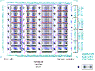
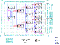
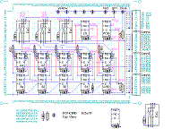
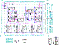
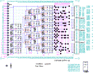
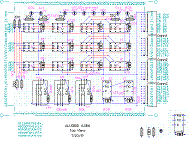
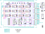
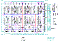
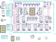
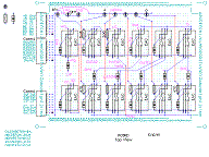
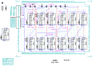
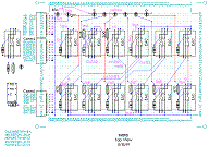
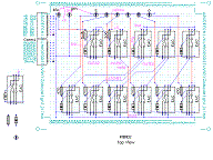
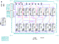
.
Gather all the parts.
Remove watch, rings, etc. and wash hands to avoid leaving fingerprints on boards. Not to sound too much like Harbor Freight, but it's a good idea to wear eye protection, especially when doing close-up soldering, which can splatter. A small fan in an open room provides good ventilation for avoiding solder flux fumes. Wash hands after handling lead solder.
Bend leads on the reed relays using round nose pliers as a strain relief. The leads are easily broken if they're bent against the case.
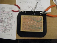 Insert and solder TINNED bus wires for traces (such as grounds) on the
underside of the board. Soldering heat expands and extends wires. Don't
pull them too hard and damage the board! Mark connections (in red) on
the drawing as they are made. Don't trim wires too short until other
connections have been made, because resoldering can loosen them.
Insert COPPER jumper wires on the top side of the board and solder them. Leave extra length on leads so they can be bent to connect to components. Joints can be reheated to bend the leads toward their connections.
Solder any connections between top copper and bottom tinned wires.
Insert and solder short parts, such as DIODES and RESISTORS. Treat resistors as polarized with their tolerance band down or to the right (for neatness). Try to bend leads on diodes so their values show. Don't solder and cut leads until their final connections are made. Solder ground connections first.
Insert machined DIP sockets for DPDT relays. The circular cutout goes up, or away from the coil end. (Dual wipe sockets are for DIP switches.) Solder a couple unused pins on each socket to hold them in place.
Insert and solder LEDs. The longer lead is the anode. Make sure the LEDs are pointed correctly before soldering. It's best to skip the green and blue LEDs on the register boards until later.
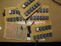 Insert edge (header) connectors with their RIBBON CONNECTORS attached.
The key protrusion goes up (away from the board) to provide proper
elevation. Use tape to hold them temporarily. Make sure their pins
protrude enough for wire-wrapping. Solder a couple unused pins to hold
the connectors onto the board. (If most of the pins are unused, solder
at least half of them to provide the support needed when plugging in the
ribbon connectors.)
Insert and solder REED RELAYS. Orient them all the same direction (for neatness). Solder their ground connections first.
Insert and solder any power jacks, switches, pots and capacitors.
Route bare leads and tinned wire around other connections to avoid any possibility of shorts. Bare wire traces soldered to the underside of the board look better and are sturdier than insulated wires. However, long traces around obstacles and connections to the edge (header) connectors are best done with insulated wire-wrap wires.
Anchor long bare wires on the bottom side of the board by soldering them at intervals to unused pads.
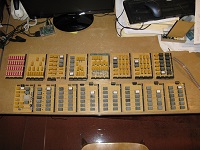 Attach wire-wrap leads to their connections in the body of the board.
Attach the inner edge connector pins first. Match cut a bundle of leads
near where they attach to an edge connector. Leave some slack, to
provide access to underlying connections. (Wire loops can hold loose
wires in place.) Attach leads to edge connectors using a wire-wrap tool.
Use a variety of colors: red for power, white for bus, and green for
control signals, for instance. Attach intermediate lengths last, so they
hold longer wires against the board.
Look closely on both sides of the board for any protruding leads, and clip them. Look closely for and fix any solder bridges or other problems.
Using a meter, verify that power (+5 and +9) and ground are not shorted.
Power-up the board and test it.
Apply labels next to LEDs. Definitely label the 5 and 9 volt power connections to prevent getting them backwards!
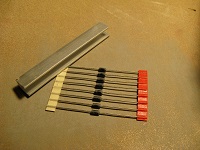 Using a section of aluminum U-channel, sand flats on both sides of a
group of eight diodes, while attached by their bandolier tape, so that
they become less than or equal to 0.10 inches wide. (This is often
necessary for DO-41 diodes so eight of them will fit side-by-side on a
DIP socket.)
Cut diodes from the tape one at a time so that their leads are all the same length. (Cutting two or more at a time results in unequal length leads that are more difficult to insert in the blue perfboard described below.)
Cut approximately a four-inch length of bare tinned wire.
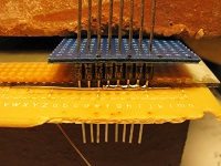 Insert the tinned wire into holes about two inches apart in a scrap
piece of perfboard. Stretch the wire tight, and bend the leads to hold
it in place. There should be at least an inch of wire protruding below
the perfboard at both ends.
Align a spacer jig to the wire. The jig is a piece of perfboard with a (metal) spacer underneath. See photo. Support the boards on a brick (or other block) to provide space for the diode leads to hang down.
Insert diodes with their cathode (band) ends up. Rotate the diodes such that their sanded flats face each other, so they will be on 0.10 inch centers.
Double check to make sure all cathode bands are up.
Insert the group of eight diodes into a second perfboard slid onto their top leads. Push the two perfboards together to firmly hold the diodes in place. Place a brick (or other weight) on top to hold everything firmly in place.
Solder the diodes (on their anode end) to the tinned wire. Melt the solder onto the diode lead first then onto the tinned wire. (Diodes require more heat than the tinned wire.)
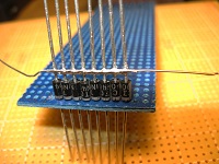 Reflow the solder across all eight diodes to make a neat joint.
Remove the spacer jig and bottom perfboard from the diodes, but don't remove the top (blue) perfboard yet.
Using side cutters, clip the diode leads flush with the soldered joint. Clip the leads at the other ends of the diodes flush with the (blue) perfboard, which leaves a 1/16th inch lead.
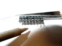 Hold the eight diodes in place with (spring closing) tweezers and a
(brick) weight. Tin (coat with solder) the 1/16th inch leads. Be careful
to not heat the diodes too much (especially the ones on the ends),
otherwise their opposite ends might get unsoldered. (Tweezers work as a
heat sink to help prevent this.)
Bend out the pins on a DIP socket slightly more than 90 degrees. The circular cutout on the socket should be to the right while the pins are bent upward.
Using the same tweezers and weight arrangement above, tin the bent pins.
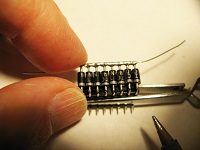 Align the tinned ends of the diodes with the tinned pins on the socket.
The soldered wire on the anode ends should face toward the center of the
socket. Hold the assembly steady against the table using the tweezers and
(brick) weight.
Fingers work much better for this than clamps. Hold half the diodes and solder the diode on the far end, This will hold the diodes to the socket. Work toward your fingers, soldering the diodes onto the socket. Hold the far end of the wire lead when soldering the last diode. (If you do this right, you won't burn your fingers!)
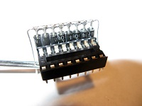 Reflow the solder joints, making sure there are no bulges of solder on
the underside of the socket pins, which need to mount flat against the
perfboard.
Use an ohmmeter to verify that each diode and its joint work correctly.
After the first few, I could assemble these modules in 15 minutes apiece. Thirty-two are needed.
Last update: 29-Sep-2019